Saturday, 23 December 2017

A Tale of Two Teardowns

Many of you will know that it's been a big few months for me. In August I made the move from Melbourne to Canberra to take on an IT Apprenticeship. It's been very challenging, but so far pretty rewarding as well, and I'm really enjoying the process of discovering my new city.

View of Lake Burley Griffin and Parliament House from Mt. Ainslie

But as with any big move, there were some hiccups along the way, including the loss of two laptops. This was... not an ideal situation... but I decided to take the opportunity to learn what makes these machines tick. They're two very different pieces of tech, and I made some interesting discoveries along the way.

Microsoft Surface 3

In 2015 this Surface 3 was an unbelievably sleek and chic 2-in-1 tablet/PC, replacing my great, hulking 15.6" Dell laptop, which was a tad cumbersome for streaming TV shows in bed. It served me very well for a couple of years, but had its share of twitches and glitches. To be fair, at least some of its issues may have stemmed from being dropped a couple too many times, and from overloading the USB port with incompatible Arduino boards... <whistles innocently>

Anyway, when it stopped charging properly I wasn't too surprised, and figured it was yet another persistent firmware or driver issue without a satisfactory solution. Then, shortly before I moved out of my place in Melbourne, I found I couldn't connect the charging cable, and realised that just about all of the pins in the micro-USB port had broken off. It was no longer chargeable.

By the time the Surface 3 was released, "computer as appliance" was the norm. The minimal profile of tablets comes at the expense of repairability, and they're basically designed to be junked at the end of the product cycle, which upsets me on principle. Microsoft customer service  told me they don't do repairs on Surfaces - economies of scale mean it's cheaper and easier to just replace them. I also called a couple of independent repair shops, who wouldn't touch it, because older Surface parts are not available in Australia (read: are totally available on eBay, but are probably salvaged or not "genuine parts"). Since my Surface was out of warranty anyway, I decided to attempt my own repairs. The challenges were many and varied:

  • Documentation was a real issue. Most resources online are about the more popular Surface Pro 3, and the internal hardware is different enough that those instructions are not entirely useful. In the end I found this repair guide on iFixit. I would definitely recommend this site to anyone doing smartphone or tablet repairs at home.

  • This device is VERY DEFINITELY NOT MEANT TO BE OPENED. I had to buy a set of specialist tools designed to melt glue and prise apart delicate, lightweight panels. I ended up adding a screen to the list of required replacement parts.
OOPS. Note the white iOpener heat pack, for melting the glue under the screen.
  • Standard screwdriver sizes didn't work for all the screws. I'm not sure why - there may be a metric/imperial discrepancy at work, but I suspect it's more likely a proprietary size. It didn't help that I'd deformed the shape of the indentations on some of the screws, after so many vain attempts to unscrew them. All of the screws had star-shaped Torx heads. Eventually, on the advice of a friend, I used a tiny, 1.0mm flat head screwdriver to get into the points of the Torx star and undo the screws.
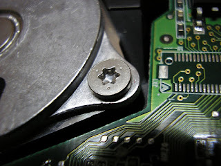
A Torx screw
After a drawn-out process which involved perusing many online instructions, gaining a great new precision screwdriver set (silver lining!), and just tearing into the machine to see what I could find, I managed to get the offending port out. A replacement will literally cost mere cents, and I should hopefully just be able to solder it into place.


The offending area, with port still attached

The dilemma comes with the replacement screen. They look simple enough to attach now that the fussy business of removing the old one has been done - there's only one connection between the tablet and screen electronics, and it's a port. They're also readily available on eBay, but at about $160-$200 they're not especially cheap. Still, it's not much compared to buying a new tablet, and it would be nice to have a second, compact display again. I may buy one some time in the new year, once I've recovered from the cost of buying a new laptop.


HP Elitebook 5730p

I purchased what is effectively a proto-Surface second hand from Connected Community Hackerspace for $50, so I'd have a Windows 7 machine for Arduino projects. Under some versions of Windows 10, the OS has trouble communicating with some boards through the serial ports. There are fixes available, but given the price, it was easier at the time to get a second computer.

And just as well I did, because I still had a computer when my Surface bit the dust. As a replacement is was slightly frustrating - it was a bit older and designed for office use, so the screen resolution wasn't great, and neither was the internal speaker - I plugged in a little Bluetooth speaker for sound. But it sufficed while I couldn't bring myself to fork out the cash for a new computer. And then I spilled a whole glass of water over the keyboard.

The teardown on this machine was a much quicker, easier and more pleasant experience than the Surface, primarily because it's an enterprise model. The Hackerspace received a bunch of them from a member whose company was upgrading its fleet. As such, the Elitebook is designed to be taken apart and have parts replaced by an IT department. There was no glue involved, and all of the screws were of the standard, Phillips head variety. I used this YouTube video as a guide.

Additionally, every part was clearly labelled with a part number, HP re-order code, and in some cases, even the name of the part. It was stupidly easy to do a web search for each part number and determine what it did, enabling me to salvage a few interesting bits and pieces:


Wi-fi and mobile broadband chips

Tiny internal speaker

Audio ports

CMOS battery - this is used to power the computer's real-time clock, so it can stay accurate even when the main power is off

I may or may not end up re-using these, but they're nice to have as souvenirs if nothing else!


The biggest prize here, though, is the 80GB solid state drive (SSD). I was planning to encrypt and dispose of it, but given that it has a standard connector and is fully intact, I'm planning to find a cable and caddy for it, so I can use it as an external drive. Score!


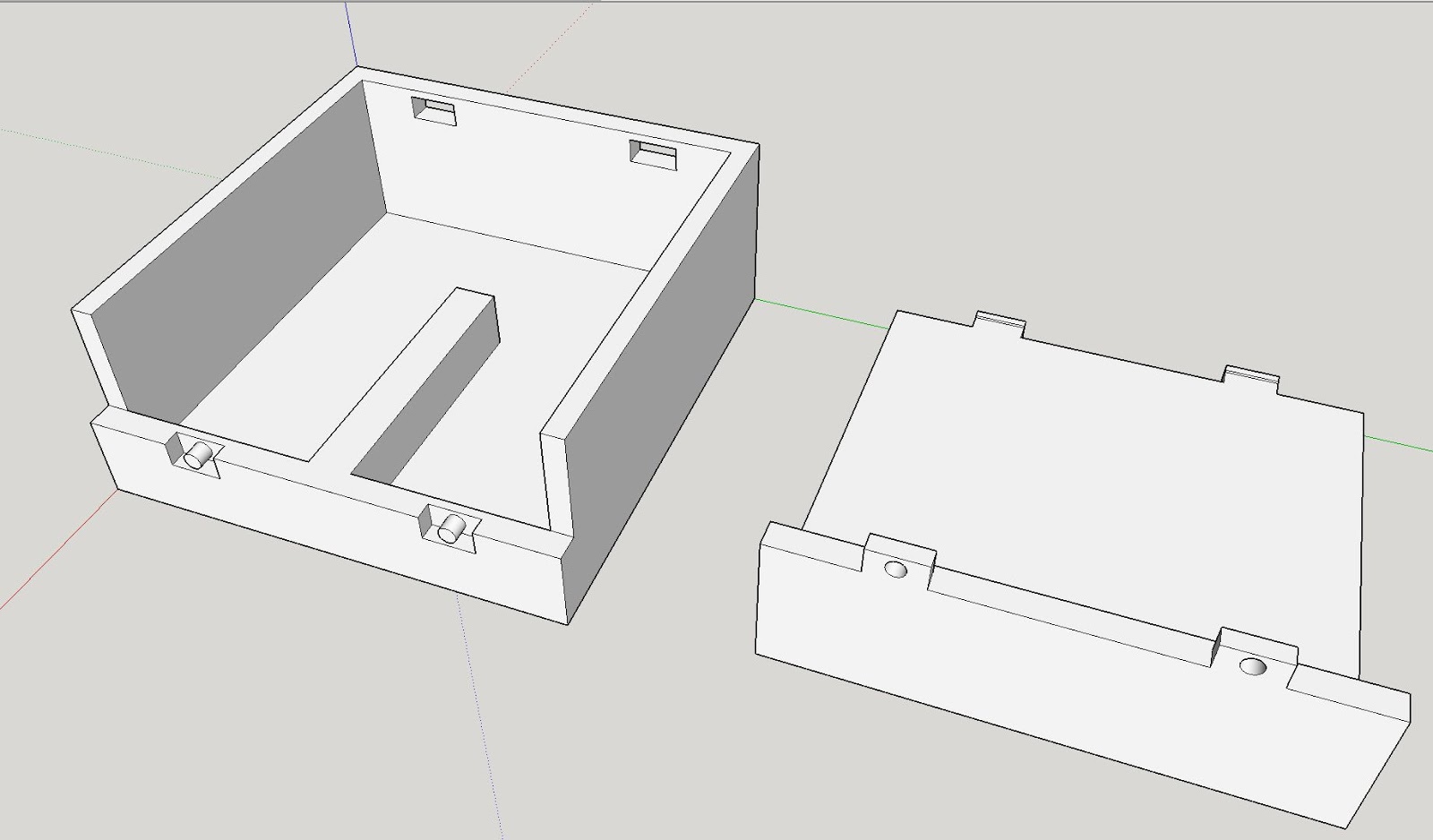
A Quick Note on Hard Drive Disposal

There is much amusement to be had in destroying a good old spinning disk hard drive. Basically, you remove the platter itself and scratch the hell out of it until it's unreadable. Some people recommend drilling holes in them, but I suspect that's more for the fun of using power tools than anything else.

These days, SSDs are most commonly used in laptops, and are really the only option for Ultrabooks and tablets because of size constraints. Short of shoving it into a blender and grinding it to smithereens, no amount of bashing and scratching will make an SSD unreadable. Security experts suggest encryption, followed by deletion of the encryption key. That way, nobody can get at the encrypted data inside.

Sunday, 11 June 2017

When Life Gives You LEDs

I've been making quite a few gifts for babies in recent months, mostly stuffed toys, and all traditional crafts. But when it came to making something for a former colleague's new daughter, I decided to mix things up a bit.

For my housewarming at my current place, I bought a pack of 50 assorted colour frosted 5mm LEDs, attached a bunch to coin cell batteries and stuck them up around the house and garden. Because buying fairy lights is for dudes. I only used about 30 of them, and have been scouting around for a use for the extras ever since. Which led to the eventual conclusion: When life gives you spare LEDs... make night lights!

5 frosted LEDs in various colours


Usually when I work with LEDs, I want to attach them to an Arduino and program them in some way. But this project was, electronics-wise at least, much simpler. All I needed was to string 5 LEDs of various colours together, and attach them to a battery pack. I didn't even need to add a switch, as I already had a battery holder with a built-in switch on hand. This enabled to me brush up on some electronics basics I've been meaning to get into for a while.


Lesson 1: Series vs. Parallel - The Ultimate Battle

I'd heard of parallel and series wiring for LEDs, and knew that how to wire my circuit would be the first decision to make here. I found a few useful resources, such as this blog post and this circuit planning tool. And my conclusion was this:


  • Parallel wiring is regular wiring. The positive terminal of the battery connects to the anodes (positive pins) of each LED, and the negative terminal connects to the cathodes (negative pins). Move along, nothing to see here. If one LED blows, the others will continue working because the circuit's current is passing along the wires that connect all the lights together.
  • Series wiring sounds to my inexperienced mind like it just... shouldn't... work... It involves daisy-chaining the LEDs in a row, connecting the positive battery terminal to the anode of the first LED, then connecting the rest cathode to anode to cathode like some kind of ungodly light bulb centipede, ending with the cathode of the final LED connecting back to the negative battery terminal. Despite my joking around, it's an effective, easy method, but has the disadvantage that if one LED blows, the circuit isn't complete anymore and will stop working altogether. 

I went with parallel wiring because a single point of failure didn't sound like the right approach here. Also because The Human Centipede scarred me for life, and I just couldn't do that to a bunch of innocent diodes.

5 LEDs wired in parallel


Lesson 2: Join the Resistance

I knew from previous projects that I'd need resistors in my circuit, as a buffer between the current coming from the battery and the LEDs themselves. This helps the LEDs last longer, and has the pleasant side effect of toning down their eye-searing full brightness.

Calculating resistor values starts with this formula:

V = I R     aka     Voltage = Current x Resistance

The formula can be transformed to calculate whichever of the three variables you don't know, so in my case I used R = V / I.

I'd tried learning about Ohm's Law previously, but it all went over my head at the time, and sewable LEDs tend to have built-in resistors anyway, so I hadn't bothered figuring it out. This blog post explained it the best for me, but I still wasn't clear on what standard resistor value that would translate to. Later on at the Hackerspace, I spoke to Andy about it and found that as we were discussing the variables involved, everything had clicked and I understood what was going on. He suggested trying out some higher resistor values as well, because the higher the Ohm value, the more of a dimming effect the resistor has on the lights. That ended up being a great call, because even frosted LEDs are extremely bright, as you'll see in my photos of the finished product.


Lesson 3: Get On Board

I've been doing electronics projects on and off for the past 5 years or so, but since I've mostly used conductive thread rather than conventional wiring, I'd never actually prototyped a project using a breadboard. I've been meaning to learn this basic technique for ages, and this was the perfect chance, because it's always a good idea to see how the resistors affect the brightness of the LEDs before soldering everything together.

I recently borrowed the Make: Electronics book from a friend, and it had a great explanation. I also found this cute how-to comic:


And here's my prototyped circuit:

LEDs and battery pack wired together on a breadboard


This may be the most useful of the skills I learned with this project. I'm keen to move onto some more complex Arduino projects soon, and being able to troubleshoot before soldering will be invaluable.


Lesson 4: Lasers Are Awesome

Well, I already knew that. But in making the frame I would mount the LEDs on, I consolidated my knowledge around how to design in 2D for a CNC laser cutter, and how best to configure the machining settings on the Hackerspace cutter to get the results I wanted.

I started with a free DXF format vector drawing of a horse I found online. I imported it into Sketchup and with a few quick adjustments turned that horse into a unicorn, surrounded it with a simple, elegant border, and defined the edges of the piece. I also added five 5mm holes into which the LEDs would slot. The Hackerspace laser cutter has reversed x and y axes in its software configuration, so I also mirrored the image to get the correct final cut:

2D drawing on a unicorn in Sketchup


The final step was to import the image into CamBam, position it in the cutting area, and create a gcode file to feed instructions into the cutting software. With the reversed Y axis, positioning the drawing correctly was a bit of a stretch for my brain, which requires me to rotate maps in the direction I'm going in order to navigate effectively.

2D drawing of a unicorn in CamBam


The Hackerspace laser cutter uses Pronterface, a 3D printing program, to feed the gcode into the machine. I used 4.5mm white acrylic for this project, which gave it a nice frosted appearance. I also cut out four straight pieces in the same material to create a frame on the back of the unicorn piece, which would hold the electronics.

There are a few things I'd change if I did it again, like allowing more time for glue to cure - I was rushing to finish it so in the end I hot-glued everything together. It held together well, but was not exactly the most elegant solution! Here's the back of the finished lamp:

Finished lamp - back


And the front (keeping in mind that reflective surfaces and lit LEDs are a bit hard to photograph):

Finished lamp - front, unlit

Finished lamp - front, lit


I was really, really happy with the final piece. If I were to make these in any quantity, I'd probably get some PCBs made to solder the LEDs to in the proper configuration - anything that involves less hot glue and more structural integrity is a good thing here! But ultimately this was heaps of fun to make, and a great learning experience.

Wednesday, 9 November 2016

Ms Fix-It

Like many people who commute on public transport, one of the banes of my existence is that moment when you realise your headphones are out of whack. Perhaps you can only hear out of one ear, or maybe you have to tie the cord in knots and hold it in a very specific position to get sound. I hate the wastage of just throwing out the old set of headphones and just buying another one, not to mention the waste of money. I wouldn't call myself an audiophile, but I do have a really decent set of compact, over-ear headphones that I love, which bit the dust some time ago.

I found this tutorial on Tested.com, and bought some replacement headphone jacks at an electronics store. This tutorial is a decent basic introduction, but it has a few omissions which I had to do more research on:
  • There are more than one type of headphone, and the different types are wired differently. You can tell immediately which type yours are by looking at the jack:

The jack with 2 rings has 3 terminals inside - for left speaker, right speaker and earth.


The type with 3 rings has 4 terminals, the extra being for a microphone - this is the type that usually comes with mobile phones.


      Ultimately, I'd suggest searching the web to find the pinout diagram for your individual model of headphone. I found out that while my headphones contain 4 cables, 2 of them connect to the same terminal on the jack:
    Image comes from here

    • The tutorial assumes that your headphone cables enclose sheathed copper wires, but mine have very fine wires with an enamel coating for insulation instead. The enamel needs to be removed before soldering. This video shows how to (CAREFULLY) burn it off, which I found worked fine:

      Apparently you can also sand the enamel off, or scrape it off using a sharp knife. Given how thin my wires are though, I feel like I'd just pull the wires apart with these methods.

    Once that part's over, the rest is pretty simple for someone with soldering experience. I happen to have a second pair of busted-up headphones of the same brand (are you seeing a pattern?) which I could practice on before hacking my good pair to pieces. And trust me, this pair is not going to be wearable again any time soon - flexible, "sports" headphones, argh:


    One last thing I must talk about is heatshrink - a plastic sleeve that (oddly enough) shrinks around your wiring when heat is applied, providing protection and insulation. I've only ever used heatshrink at the hackerspace, using a heat gun or a blower attached to a soldering station. I didn't think a hairdryer would be hot enough for this application. But when I asked at the electronics shop, the salesman told me most people use hairdryers.

    I have short hair and am super-lazy with the whole beauty routine thing anyway, so I didn't have a hairdryer. But my mum had a spare. Allow me to present the one thing every modern gal needs in her toolbox: this swell vintage General Electric compact hairdryer! Impress that special man in your life with your fabulous coiffure and ability to fix small appliances!


    And it worked... kind of OK? The heatshrink shrunk, but it took a while (the hairdryer overheated and cut out, so it had to cool down before I could use it again) and came out a little lumpy - it didn't help that I bought heatshrink with too large a diameter. I'd say the hairdryer's fine for most things, and I'll definitely keep it around for future use. But in this case, the finished piece needs to fit snugly inside the cover of the headphone jack. Off to the hackerspace for the final job then.

    *****************

    And now, after some quality time with a proper soldering station, I can hear bass again!! I'm so happy with this!!!!!!


    Tuesday, 25 October 2016

    Softie Party!

    There's something of a baby boom going on in my social circle at the moment. Now, I don't know much about babies, and anything I have that might be called a maternal instinct seems to have been redirected toward cats rather than humans. But one thing I do know is that kids like soft toys, which means IT'S SOFTIE MAKING TIME!

    A couple of instances of design number 1, a squishy rocket ship, have already been deployed to their tiny new owners, hopefully helping to instill their parents' love of sci-fi from the very beginning. As with any space-bound vessel, the first step was to produce some engineering drawings:


    Rocket ship toy drawings

    This was just to get a rough idea of the size, shape and fabrics I'd be using. After I had that all worked out in my mind, I made pattern pieces on baking paper, which I used to trace the shapes in dressmakers chalk and cut out my fabric:

    Cut out fabric shapes for sewing

    It's nothing fancy as patterns go, just flat shapes with decorations. I like to use fleece and felt fabrics, because they're huggably soft, really easy to work with, and very forgiving of a few uneven stitches. The red and black "window" pieces go onto one of the grey rocket body pieces first - and what's a window without someone to wave out of it? I found a couple of these adorable iron-on robot patches at the fabric shop:


    Here you can see the window and its occupant (I had to do a bit of surgery to make it fit), and some "rivets" stitched in metallic embroidery thread. After joining the rocket body to the exhaust flames, I stitched around the outside using buttonhole stitch, adding in a ribbon for hanging the finished piece:


    Buttonhole stitch may not look as professional as a hidden seam, but it's easier to do, and I quite like the homemade, hand-stitched look it gives to the finished pieces.

    Then comes the fun part, stuffing! I use a fluffy polyester stuffing, and a chopstick to jam it into the hard-to-reach parts, like the fins on the rocket.


    After stitching around the last of the stuffing, here's what this finished product looks like. Something tells me the recipients don't care that much about them yet, but hopefully they'll enjoy the cuddliness when they get a bit older.


    My next plan is to make some animal softies for more small humans. Today I found this embossed fleece fabric, which has definitely given me some more softie inspiration!


    Saturday, 20 August 2016

    I Can Haz Surveillance - Part 2

    Part 1

    This is how my DIY projects often go: I have a burst of creativity and enthusiasm, do some research, learn some things. Then I put the project down, intending to come back to it soon. "Soon" usually turns out to be a few months later.

    In the last couple of weeks, I've decided to pick up my cat GPS project in earnest again. In the intervening time I've tinkered intermittently, and managed to solve a couple of problems:

    • The finished unit will have to be as small as possible. I replaced the Flora board, which is inconveniently large and round, with an Arduino Pro Mini, which has a much slimmer profile. It's a simpler board without built-in battery connector or switch - I consider this a positive because the layout of my circuit is more flexible. I also found instructions for getting the GPS to talk to a non-Flora microcontroller and got them talking, which I consider a small triumph.
    • I was concerned about what type of battery to use. The easiest type to attach to a wearable project is a Lithium Polymer (LiPo) battery, but these aren't the most stable. If it's secured firmly into place within an enclosure, no harm should come of it, but still, you can't tell a cat to be careful and I don't want to risk injury. On the other hand, using the equivalent voltage in normal household batteries would make the unit heavier. In the end I settled for a Lithium Ion battery, which is more stable, and also comes in a 3v version, meaning I only have to use one battery. Also loving the pun of fitting a cat with a Li-ion battery (RAWR!)

      I started out with a larger battery that, based on its milliamp hours (mAh), would definitely stay charged for an entire day of cat frolicking. Now though, I've decided to settle for a smaller battery (actually a camera battery) which weighs less but won't last as long. We'll see how that one goes - it's all experimental for now.


    The next phase is to create an enclosure for the components. This will need to be weatherproof, and strong enough to survive having a cat's weight on top of it. Some Hackerspace friends have assured me that the GPS module needs radio line-of-sight to the sky, but not necessarily visual line-of-sight. So I've designed a lidded case to be 3D printed in ABS plastic, which is light and strong:


    The raised bar in the middle of the case is where I'll mount the Arduino and GPS module, using Blu-Tac so I can easily remove them and download the data. Depending on how well the fasteners work, I may have to gaffer-tape around the case while it's in use, to make sure it's secure.

    Once I've put this together, I'll be able to walk around with the unit and test how well it logs data when fully enclosed. If that works, I'll tweak the design so I can mount it on a cat collar. Stay tuned!

    Friday, 29 January 2016

    The Astounding Canine Torch

    It started as a joke over the dinner table. My sister and her partner mentioned that they were trying to do a jigsaw puzzle, which was made more difficult by the poor lighting at their house. At the time, I happened to be finding my way around an Arduino Lilypad light sensor that I'd bought ages ago but hadn't used yet. Since I'm already working on fitting their cat Georgie with a DIY GPS tracker, I joked that I could attach a light sensor and a few LEDs to their dog Cleo, turning her into a night light that would activate when the light levels in a room got too low.

    I should say at this point that I usually disapprove of putting animals in costumes. They look so unhappy and uncomfortable, and I just feel sorry for them. This random Internet cat is a case in point:


    On the other hand, wearables for animals are super-cute, and provide some fascinating logistical challenges. Plus, Cleo wears jackets and harnesses all the time, and doesn't seem to mind. She even sleeps in "pyjamas" in winter, because her short fur doesn't give her much insulation.


    So. The scene was set, the challenge thrown down.

    I would have liked to mount this arrangement to a sturdy fabric harness, but the only ones I could find were far too expensive for a quick novelty project like this one. In the end I opted for a cheap doggie t-shirt from Target. It didn't sit very well in place, and if you're looking to make something for more permanent use, I'd definitely recommend investing in a harness, jacket or other appropriately strong and durable dog apparel that can still be sewn onto. As for the electrical components, I used some bits and pieces I already had in my box of tricks:

    DFRobot Beetle microcontroller
    Battery holder (3 x AAA) with built-in on/of switch
    Lilypad light sensor
    4 x sewable white LEDs
    Conductive thread

    I sewed a felt pocket to the top edge of the shirt to hold the battery pack. It's important when working with animals that you use stable, protected batteries that can be safely knocked around, batted, rolled on, etc. etc. without rupturing or causing any other damage. I would NEVER use lithium polymer (LiPo) batteries on fur babies, as I feel this would most likely end in pain for the animal in question, and vet fees (or at least a healthy amount of guilt) for his or her human.

    So, here's the final arrangement:


    The LEDs are wired in sequence so they're all controlled from the same pin on the microcontroller, and all light up simultaneously. You'll see I insulated the conductive thread with cloth tape, partly to hold it in place, and partly to stop it from coming into contact with Cleo's body. I also completely taped over the circuit on the inside of the shirt. Conductive thread is basically uninsulated wire, and while the voltage involved isn't high enough to hurt an animal, contact with fur could potentially cause a short circuit, which is never pleasant.

    The software I used is nothing too fancy - just the code provided by Sparkfun for a connection between microcontroller, sensor and LED, pretty much unaltered. This code allows the sensor to take an analog read, which produces a stream of numbers in the Arduino IDE's Serial Monitor, reflecting the ambient light levels around the sensor. A "darklevel" is defined, which determines the reading at which the room is considered dark. The code uses the darklevel to trigger the LEDs on when the sensor readings dip below a certain number.


    I changed the pins to reflect the way I'd connected the sensor to the Beetle (the code is written with a Lilypad Simple in mind), and I also changed the darklevel value to reflect the house this ridiculous device would operate in. Every space has different "normal" ambient light levels, so any project using a light sensor has to be specifically calibrated to its environment.

    And here's the very patient Cleo, lighting up the room even more than she usually does with her adorable presence:


    Overall, the doggie night light worked OK, but as I said earlier, it would work much better on a sturdier base than the t-shirt. Conductive thread circuits behave inconsistently when they bend in unpredictable ways. If I hadn't been in such a hurry, I would also have attached the battery pack much more securely, so it couldn't jiggle around so much. Ultimately though, I'd count this as a pretty successful initial prototype. If you could securely connect it to your dog's harness it could be a nice accessory for evening walkies - although in that case I'd recommend adding a clear, waterproof covering over the components.


    I'd like to take this opportunity to thank Lisa and Andrew for kindly allowing me to experiment on their animals - in a way that I'm certain would be approved by any reasonable ethics committee.

    Monday, 30 November 2015

    I Can Haz Surveillance?

    I've been wanting to experiment with gathering GPS data for a while, and last week I got myself a wearable GPS Module made by Adafruit:


    It's not the cheapest option (once you get it to Australia, anyway), but I'm very familiar with the Flora platform by now, and this is a very self-contained solution. It's got built-in data logging capabilities, so basically you wire it to the microcontroller, load the logging program, and away you go. It's also got an internal antenna. To get a location fix, the antenna needs to have direct line-of-sight to the sky, which brings with it the unique and pleasant opportunity to do electronics work outside:


    I found the online instructions quite easy to follow. There's a ready-made software library which includes programs for capturing and downloading GPS data from this module. Here it is in the Arduino IDE:


    1. Load leo_locus_status to the microcontroller to begin logging data.
    2. Once you've gone outside and logged some data, load leo_locus_dumpbasic to download the coordinates. More on what to do with this below.
    3. To erase the existing data on the GPS module, load leo_locus_erase.
      It doesn't mention this in the Adafruit instructions, but if you forget to erase your last dataset before creating a new one, the next set of coordinates you download will also include your last trip.
    The raw data looks pretty daunting, but with a few simple steps you can plug it into Google Maps, getting a user-friendly visualisation of your journey:
    1. Parse the data - Adafruit provides a simple online tool for this.
    2. Copy the data marked "KML Output," paste it into a text file and save it.
    3. Go to My Maps - a functionality of Google Maps - which gives you an option to import the KML file. Contrary to Adafruit's instructions, I found I had to re-save your text file with the .kml extension before you can import it.
    Another really useful tool I found was this GPS coordinate converter. Coordinates can be formatted in several different ways, and if you directly paste a set of coordinates from you dataset into Google Maps, it won't recognise it. It also helps to jump onto Wikipedia and get a rundown of how coordinates are expressed and what they mean.

    Back on the hardware side, this is my completed GPS logging set-up. The black battery pack fits inside this little pocket, and holds 3 AAA batteries, which can power the Flora microcontroller for hours at a time. The coin cell battery is to give the GPS module a boost as it powers up and gets a fix.


    There's a brooch pin on the back, which I used to fasten this to the outside of my handbag as I took a train journey from West Footscray to Mount Waverley. Not suss at all...

    Click here to see my path. Once I zoomed in on the route, I was impressed with the amount of detail that came out. This is me arriving at Flinders Street Station, walking around on the platform, getting food on the concourse and walking down to another platform to catch the connecting train:


    Pretty awesome, in my opinion. On the other hand, I clearly did not fly over from Flinders Street and land on one of the platforms, as the path indicates. Still, I'm very happy with the story this visualisation tells.

    But you're probably wondering, WHY? Well, there's not always a "why" to a maker project, but in this case there is, and it's this gorgeous creature:


    Meet Georgie, my sister's cat (or as I prefer to call her, my fur-niece). She's mostly an outdoor cat, leaving the house when the humans get up, and returning whenever she damn well feels like it - sometimes quite late at night. I stayed with her and her humans for a while earlier this year, and couldn't help but wonder where she went while she was out. A couple of months later I watched the Cats Uncovered documentary on SBS, in which three groups of cats (city dwellers, village cats and farm cats) had GPS trackers and cameras attached to them, so that researchers could collect data on their movements and interactions. At that point, I knew I'd have to impose on Georgie at some point.

    There will be two major challenges to getting this project ready for cat deployment. The first is form factor: My current arrangement is simply way too big for a cat. I have some tiny microcontroller boards which could work, although I think I'll have to use a voltage regulator (the component on the right) since they're both 5v boards, and the GPS module is made to work with a 3.3v board:


    Ultimately though, the biggest component is the AAA battery pack, and I'm not sure there's much can do about that. Here's where I consult the wise denizens of my Hackerspace.

    The second, and probably bigger, challenge is getting and keeping the device on the cat. Georgie is not a huge fan of collars anyway, and has found her way out of many of them. My sister suggested we get a harness rather than trying to attach the module to a collar, and keeping the whole device as small and light as possible can only help. There'll definitely be some fittings and testing around the house before I can start collecting the really interesting data.

    Stay tuned for more - hopefully Georgie will still be talking to me when this is all over.