Friday, 6 September 2013

Extruder Blues

I admit I haven't paid a huge amount of attention to my printer recently. Part of that is because I've hit some issues with my peristaltic pump extruder.

Soon after my last post I got my stepper motor and tubing in the mail. Two kinds of tubing are needed for this extruder: Flexible silicone tubing to feed through the pump, and rigid PTFE (aka Teflon) tubing for the nozzle. I fed in the tubing like this, using about 32mm of the PTFE tubing at the end:

Peristaltic pump extruder with tubing fitted


Here's what it looks like when assembled. The pump works by squeezing the soft, silicone tube around the large herringbone gear to create a vacuum.

Peristaltic pump extruder with tubing and large gear fitted

A small gear is fitted onto the stepper motor shaft, and which fits through the large hole to the left of the tube housing. When the motor runs it turns the large gear, which pumps the material through the tube and extrudes it out the other end.

Before going any further I decided to test out the mechanism manually by putting the end of the tube into a glass of water and turning the large gear with my hand... and nothing happened. The gear wasn't squeezing the silicone tube enough to make it airtight, so there was no suction. I was using exactly the same size of tubing as the designer of the pump did (2mm internal diameter, 4mm external), so the difference was in the material the tubing was made of. He didn't care whether his tubing was foodsafe, so he bought it from a local aquarium supplier. I would guess that his tubing wasn't as soft as mine. To fix this problem I could look around for some different tubing, but there are only so many foodsafe options, and only so many places where I can buy short lengths (I only need a metre or less at a time).

The other option is to modify the design for the large gear, moving the location of the bearings outward by fractions of a millimetre, 3D printing and testing the redesigned part, then repeating the process until the right pressure is reached and the pump works. That wouldn't worry me since I've been improving my SketchUp skills a lot recently. But about the same time I realised I'd also have to modify the main body of the extruder, adding bolt holes to mount it securely to the ORD Bot's extruder carriage. Again no big deal, but it begs the question: If I'm redesigning every part of the extruder to work with my equipment, wouldn't it just be better to find a more appropriate (not to mention a more tried-and-tested) model? There are plenty of open source paste extruders out there, the best known being the Makerbot Frostruder. At the moment I'm trying to motivate myself to research the options. More on that some time in the future.

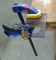
In the meantime I've been pretty idle where the ORD Bot is concerned, but I have done a couple of useful things. Firstly, I laser cut and installed a fan mount above the RAMPS board. The fan is essential because the RAMPS board heats up as it runs, so it needs to be cooled down in order to run safely - just like any computer processor, really. The fan mount is designed to be laser cut as a flat piece, then clamped down and bent to a 90 degree angle using a heat gun:

Laser cut fan mount clamped to table


Laser cut fan mount clamped to table, bent with heat gun

The design is up on Thingiverse. And here it is mounted on the printer:


I've also managed, after several unsuccessful attempts, to design and print a mount for the x-axis endstop:


The final design is based on my existing y- and z-axis endstop mounts, which were designed by a member of my hackerspace. It's not 100% perfect, but it'll serve its function. I just have to find a slightly shorter bolt to properly secure it to the gantry.

At the moment I'm preparing to move house, so I'll be putting the printer building on hold for  bit longer. Who knows what ideas I'll come back with? Only time will tell...

Saturday, 20 July 2013

Pump It Up (Extruder Build Part 1)

For my extruder, I'll be using a 3D printed peristaltic pump extruder found on Thingiverse.  The designer of the pump has an awesome 3D printing blog and his designs are great - probably because he seems to test most of them out on his own RepRap.

That said, this extruder is a work in progress.  There isn't any comprehensive documentation on building it, so I worked from pictures on Thingiverse and the blog post about this design, and asked my ever-helpful Hackerspace colleagues to help me interpret what I was seeing.

To complete the pump I'll need a stepper motor and tubing, which have been ordered but are still on the way.  Here's my step-by-step guide to assembling RichRap's Geared Peristaltic Pump Extruder up to that point:

You'll need the following materials:
  • The 3D printed extruder parts
  • M3 bolts (3 x 25mm, 1 x 20mm, 2 x 15mm), washers and nuts
  • M4 bolts (1 x 50mm, 5 x 20mm), washers and nuts
  • 624 bearings (7x)

To build the extruder:


1.  Arrange the 3D printed wheel and large gear with five of the bearings like this:

2.  Screw them together with the 20mm M4 bolts, then insert the 50mm bolt through the centre hole:


3.  Put the main body of the extruder and the cap for the tube housing together.  Attach them using a 25mm bolt on the left side and a 20mm bolt on the right side.  The nuts sit in specially designed slots at the foot of each screw hole.


4.  Attach the nozzle section using the 25mm bolts on the front of the extruder, and one 15mm bolt to secure it on the underside.  Again, there are slots for the nuts to fit into. The other 15mm bolt goes through the bottom of the nozzle and will hold the tubing in place.


5.  Thread two washers and a bearing onto the end of the 50mm bolt and fit them into the bearing-shaped recess in the main body:


6.  Fit another bearing into the recess on the back of the extruder, and secure it with a nut.


And that's the end of part 1 of extruder construction!  I'll post part 2 when the motor and tubing arrive.  Here's what it looks like so far:


One quick note: I modified the nozzle section, cutting off a few millimetres at the edges to make it slightly narrower overall.  This will let it fit neatly into the gap in the ORD Bot's extruder carriage.  This extruder is designed to fit into a 3D printed quick-release carriage, but rather than modifying that to fit the ORD Bot, I'll just drill some extra holes in the extruder and existing carriage.

Sunday, 30 June 2013

The ORD Bot's New Clothes

My hackerspace's laser cutter has recently come online after extensive repairs, and it's now the go-to tool for everything, because nerds love lasers.  Also because, for a group of people used to often waiting at least an hour to get a basic design manufactured on a 3D printer, the concept of getting something out of the laser cutter within five minutes is irresistible.

I too have jumped on this convenient bandwagon, and decided to make my printer's build plate, LCD display mount and fan mount (to cool the RAMPS board) out of laser cut acrylic.

Step one was meticulously measuring up the ORD Bot and designing the pieces.  I used SketchUp, which is one of the most user-friendly free CAD programs out there.  I've designed one piece in SketchUp before, but that was a while ago so I had to learn the basics all over again.  I actually think designing for a laser cutter is a great way to start with CAD, because the designs are 2D.  So you can get used to how a 3D design interface works, how to pan and zoom around your design, how to make sure you're drawing your shapes on the correct plane, etc. without the added complexity of three dimensions.

I ended up using two of my three designs - the fan mount needs a bit of extra work.  Here are my SketchUp models for the build plate and LCD mount:


I then exported the models as DXF files and opened those in CamBam, where I smoothed out some rough edges and created a file that could be used to plot a toolpath for the laser cutter.

As you can see the designs aren't complex, but they had to be millimetre perfect to be able to fit onto the ORD Bot, which has pre-cut mounting holes.  So I was delighted and extremely proud of myself when the finished products ended up fitting really well:

Build plate

Since I won't be using a heating element, which would usually go between the blue anodised aluminium plate and the actual build surface, I suspended the build plate on nylon spacers.  This will give me room to clip baking paper to the acrylic surface, for better food safety.

LCD mount

The LCD mount fitted a bit differently than I anticipated.  I designed it to be fastened to the ORD Bot's back plate with four bolts for extra security when the entire machine starts vibrating with the force of five stepper motors.  In the end I had to move the mount up a little to fit it around the Makerslide frame, so it's only fastened with two bolts.  It seems secure for now, but I'll keep an eye on it when I start using the printer.

I've also fitted the endstops on my Z and Y axis, using mounts made by a kind hackerspace colleague.  I decided to use mechanical endstops because they're simpler than the optical or magnetic options.  If one of the axes should reach its limit, it will hit the metal switch and stop the print, like so:


The endstop mount for the X axis needs redesigning, so more on that - and the redesigned fan mount - later.

Saturday, 1 June 2013

Baby's First Steps

It's been a while since I last posted, but that doesn't mean nothing has been happening. I've finished connecting the wiring for the stepper motors, and am currently in the process of sourcing bearings, bolts and tubing so I can assemble my extruder and its carriage. I've also got some STL files for 3D-printable endstop mounts, which I'll get around to printing and testing at some point... Because this is all unfamiliar I'm taking things slowly at the moment.

Since all the motors are hooked up now, I connected the printer to a power supply last week (with supervision of course). The good news is that all the motors are in working order, yay! Here's a very short video of my printer's first movements:


Like most babies' first steps, hers were jerky and hesitant. Unfortunately this is at least partly because the threaded rods on the z axis aren't 100% straight - it's such a slight bowing that a human can barely see it, but it's more than enough to upset a robot. After a bit of oiling things started to run more smoothly, but needless to say I'll be keeping an eye on this.

Obviously there are a few things on the go right now.  I'll report back when something else interesting happens :p

Monday, 13 May 2013

Making Connections

Amongst the many helpful ideas I've received from my hackerspace colleagues, was the suggestion that I use polarised connectors on my printer's wiring rather than just soldering everything together. The idea is to give me more options for the configuration of the wires.  I can either keep them long and thread them through the gaps in the Makerslide rails so they're mostly invisible, or (more likely) I can easily crop and re-connect the wires at a later time so they fit neatly around the back of the frame.

I couldn't find any step-by-step instructions online for fitting the connectors, so instead I asked for an in-person tutorial. This was probably a better option for me anyway because one of the ways I learn is by asking questions. Annoying, maybe, but super-effective. I rarely end up asking the same questions twice.

Thanks to my patient instructor, I can now present the official Robot Lady Beginners Guide to Polarised Connectors. You will need these components:
  • The wires in question
  • Male connector, a.k.a. header
  • Female connector, a.k.a. housing
  • Crimp pins
  • Heat shrink
  • Solder
And these tools:
  • Soldering iron
  • Pliers and/or crimping tool
  • Heat gun
  • Helping hand

Step 1:  Cut small pieces of heat shrink and slide one onto each of the wires coming out of the machine. Then spread a tiny amount of solder on each of the header pins (the bent ends), and the exposed end each of the wires. This is called tinning, and will help with the next bit.

Step 2:  Use the helping hand to clamp your header in place. Hold the soldering iron against each pin to melt the solder and secure each wire to a pin:

Yay, I did that!

Try not to burn the crap out of your header casing like I did though:

In my defence, the last time I did any soldering
was about a year ago, and I was a beginner.

Step 3:  Push the heat shrink up until it covers the exposed wires and pins, and use the heat gun to make it shrink into place:

If anyone gives you crap about how girlie girls and electronics
don't mix, remind them that their manly "heat gun" is really just
a glorified hairdryer.

And there you have it - a finished header piece.

Woohoo!

Step 4:  Now for the housing, which fits onto the wires not yet connected to the machine. Put a piece of heat shrink around each wire, then place each wire in turn into a crimp pin like so:

So tiny...

Using needle nosed pliers or a crimping tool, very carefully fold down the tabs one at the time so they secure the wire in place. You can apply a tiny bit of solder to secure the wire further if you like.

Step 5:  Cut the crimp pins apart and remove the excess tabs of metal at the bottom. Slide each pin one at the time into the housing until it clicks into place. Be careful to put them in the right order so that when you connect the header, the same coloured wires all line up. Then push up the heatshrink until the ends jam into the holes in the housing, and shrink them into place.  Housing done!

Et voila.

You can now connect the two sides of your connector!

So now the Y-axis and one of the Z-axis stepper motors are connected to my RAMPS board, which I had previously mounted onto the printer.  The wires are unfeasibly long at the moment:

Good thing I came up with an innovative storage solution...

But that's a good thing while I get everything working. Later on I can just crop the wires coming out of the RAMPS board and fit new housings.

Monday, 29 April 2013

Just Following Instructions

Before I began assembling my ORD Bot's mechanical frame, I assumed that it would be a bit like putting together a particularly complicated piece of IKEA furniture.  I expected to have to do some research on the parts involved.  I expected the process to be unfamiliar and fiddly, and to make mistakes along the way.  But essentially I expected that I would be following a set of comprehensive instructions that would give me enough detail to slog through it on my own without too much help, despite being a total noob.

I started on Thursday using the ORD Bot Wiki as my guide.  Yes, I know what a wiki is, but I was wide-eyed and optimistic nonetheless.  Here are just some of the challenges I faced:
  • The instructions assumed assembly from scratch, and my frame came partially assembled.  It took me some time to work out which instructions to follow and which weren't relevant.
  • Where the instructions referred to a specific part, I often had no idea what it looked like.  For example, apparently this is an eccentric spacer:


The picture in my head was something more like this:


  • The diagrams are all engineering drawings, which means they're very accurate and meticulously labelled.  Unfortunately I've never had to interpret engineering drawings before.
  • The wiring instructions say you should do the wiring "very early in the build", but don't actually say where the wires have to end up and how they connect to their destination.
  • There are two sets of assembly instructions for the main frame and z axis.  The first is more technical, but is complete.  The second is more noob-friendly but missing some vital steps.
I managed to fit most of the pieces together though, dismissing the wiring for the moment and concentrating on the frame itself.  And then my partner came home.  Having done a lot of work on our Makerbot, he found a couple of problems I didn't pick up on:
  • The build platform was wobbly.  I figured I could fix it later, but he immediately realised that one of the eccentric spacers underneath was out of alignment.  Problem solved!
  • The z axis motor shafts weren't aligned properly with the nut blocks (that's not innuendo, but it should be).  We had to unscrew the motor mounts and move them a couple of millimetres further out.  On one side this worked fine.  On the other side it had been screwed in too tightly (more wasted innuendo...) and couldn't be budged by hand.  Construction had to stop until we could get to the hackerspace and find a drill.
Fast forward to Saturday at the hackerspace, where my partner grabbed a Dremel and tore the offending screw a new one, converting it from a hex socket to a flat slot:


This provided enough leverage to take the screw out and move the motor mount.  Then I attached the couplers and leadscrews, and started manually turning them to move the gantry down.  Success!

Or so I thought, until a kind visitor to the hackerspace suggested that I test the various parts of the frame with a level, which showed that the different axes were out of alignment.  Luckily, he also knew how to remedy the situation.  So this is what my robot looks like now:


TLDR: When IKEA release their own 3D printer range (you know they will eventually, and it'll have a maddening faux-Scandinavian name with gratuitous diacritics, like Ekstrüüdå) I want to get my hands on their instruction booklet.

Now, on to the extruder and electronics *eye roll*

Wednesday, 24 April 2013

Poetry in Plastic

Last night I received some of the parts for my extruder:


These parts are extra special because they themselves are 3D printed, by one of the resident gurus at my hackerspace. To me there's something supremely poetic about printers printing other printers. Although that may just be the alliteration...

Creating a self-replicating machine is one of the stated goals of the RepRap project. To me it's a fascinating and inspiring vision - one of those points where science fiction meets real life. We're not there yet. Most 3D printer components are still made of materials that you simply can't manufacture on a hobbyist machine. But there are some highly innovative people in the RepRap community, so it could happen some day. The latest step is the invention of this printable stepper motor:


What a time to be alive.

Wednesday, 17 April 2013

Foxy Unboxing

After a somewhat epic trip across the city and back, today I picked up my ORD Bot and brought it home.  The box was surprisingly small and light, but all the ingredients were in there:

Unopened ORD Bot box
The box itself, freshly arrived from the exotic Orient.

Kit in packaging, first layer
Inside the box, layer 1 - RAMPS
kit, heated bed and part of the frame.

Kit in packaging, second layer
Inside the box, layer 2 - The rest
of the frame, wiring and endstops.

Electrical components
Close-up of the electricals.  The RAMPS
kit I bought includes a display.

Endstops
Close-up of the endstops - one set of
mechanical and one set of magnetic.

Allen key in packaging
The tiniest Allen key I've ever seen!

All ORD Bot parts unpacked.
The whole assemblage.

The ORD Bot kit doesn't come with an extruder, which is part of why I chose it since I'm going to fit it with a paste extruder anyway.  Initially I'm planning to use a peristaltic pump, which seems to be the simplest option to start off with.

Let the assembly begin!

Sunday, 14 April 2013

And So It Begins...

A year or so ago, I discovered 3D printing when my partner introduced me to Makerbot and suggested we get one of our own.  I'm a crafty person by nature, so the prospect of an entirely new form of making things was immediately inspiring.  We soon welcomed a shiny new Makerbot Thing-O-Matic into our lives and thus began a new obsession.

It was only a matter of time before I discovered Makerbot's frostruder, an extruder made specifically for printing frosting onto cupcakes.  And yes, turning CAD drawings into solid plastic objects is mind-blowingly amazing, but turning them into something you can eat is exciting on a whole new level.  Eventually I also found out about RichRap's experiments in paste extrusion.  He begins with a range of edibles and then steps it up a notch, printing in porcelain clay which can then be fired.  It was at this point that I decided I needed to get in on the action.

So to cut a long story short, I've recently ordered an ORD Bot Hadron (or as I like to think of it, the prettiest of the RepRaps), which I'll be fitting with a paste extruder.  I'll be using this blog to share my learning process as I assemble my 3D printer and experiment with extrusion methods, feedstocks and CAD design.  Since I'm a almost a complete newbie at these things, there will be a lot of learning to share.  If the mood takes me I might also talk a bit about hackerspace culture and the world of hobbyist 3D printing.

Posts will happen whenever I feel like it, but please check in every now and then to share in my adventures.