I admit I haven't paid a huge amount of attention to my printer recently. Part of that is because I've hit some issues with my peristaltic pump extruder.
Soon after my last post I got my stepper motor and tubing in the mail. Two kinds of tubing are needed for this extruder: Flexible silicone tubing to feed through the pump, and rigid PTFE (aka Teflon) tubing for the nozzle. I fed in the tubing like this, using about 32mm of the PTFE tubing at the end:
Here's what it looks like when assembled. The pump works by squeezing the soft, silicone tube around the large herringbone gear to create a vacuum.
A small gear is fitted onto the stepper motor shaft, and which fits through the large hole to the left of the tube housing. When the motor runs it turns the large gear, which pumps the material through the tube and extrudes it out the other end.
Before going any further I decided to test out the mechanism manually by putting the end of the tube into a glass of water and turning the large gear with my hand... and nothing happened. The gear wasn't squeezing the silicone tube enough to make it airtight, so there was no suction. I was using exactly the same size of tubing as the designer of the pump did (2mm internal diameter, 4mm external), so the difference was in the material the tubing was made of. He didn't care whether his tubing was foodsafe, so he bought it from a local aquarium supplier. I would guess that his tubing wasn't as soft as mine. To fix this problem I could look around for some different tubing, but there are only so many foodsafe options, and only so many places where I can buy short lengths (I only need a metre or less at a time).
The other option is to modify the design for the large gear, moving the location of the bearings outward by fractions of a millimetre, 3D printing and testing the redesigned part, then repeating the process until the right pressure is reached and the pump works. That wouldn't worry me since I've been improving my SketchUp skills a lot recently. But about the same time I realised I'd also have to modify the main body of the extruder, adding bolt holes to mount it securely to the ORD Bot's extruder carriage. Again no big deal, but it begs the question: If I'm redesigning every part of the extruder to work with my equipment, wouldn't it just be better to find a more appropriate (not to mention a more tried-and-tested) model? There are plenty of open source paste extruders out there, the best known being the Makerbot Frostruder. At the moment I'm trying to motivate myself to research the options. More on that some time in the future.
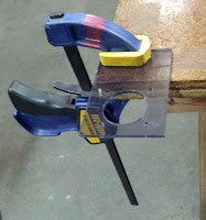
In the meantime I've been pretty idle where the ORD Bot is concerned, but I have done a couple of useful things. Firstly, I laser cut and installed a fan mount above the RAMPS board. The fan is essential because the RAMPS board heats up as it runs, so it needs to be cooled down in order to run safely - just like any computer processor, really. The fan mount is designed to be laser cut as a flat piece, then clamped down and bent to a 90 degree angle using a heat gun:
The design is up on Thingiverse. And here it is mounted on the printer:
I've also managed, after several unsuccessful attempts, to design and print a mount for the x-axis endstop:
The final design is based on my existing y- and z-axis endstop mounts, which were designed by a member of my hackerspace. It's not 100% perfect, but it'll serve its function. I just have to find a slightly shorter bolt to properly secure it to the gantry.
At the moment I'm preparing to move house, so I'll be putting the printer building on hold for bit longer. Who knows what ideas I'll come back with? Only time will tell...


No comments:
Post a Comment